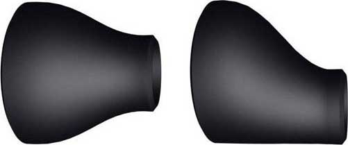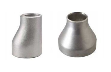
Dimensional Tolerances of Concentric and Eccentric Reducers (ASME B16.9)
The ASME B16.9 standard specifies dimensional tolerances for factory-made wrought butt-welding fittings, including concentric and eccentric reducers. These tolerances ensure uniformity, accuracy, and compatibility across various piping systems. Below is a detailed breakdown of the tolerances applied to concentric and eccentric reducers as per ASME B16.9.
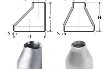
1. Dimensions and Terminology
Before diving into tolerances, it’s essential to understand the key dimensions of a reducer:
| Dimension | Description |
|---|---|
| D1 | Outside diameter of the larger end of the reducer. |
| D2 | Outside diameter of the smaller end of the reducer. |
| L | End-to-end overall length of the reducer. |
| T | Wall thickness of the reducer, which should match the pipe thickness (schedule). |
| Eccentricity | For eccentric reducers, the vertical offset between the larger and smaller ends. |
2. Dimensional Tolerances
The following table summarizes the key tolerances for concentric and eccentric reducers as specified by ASME B16.9:
| Dimension | Tolerance |
|---|---|
| Outside Diameter (D1 and D2) | ±1% of the specified outside diameter or ±3.0 mm (whichever is smaller). |
| End-to-End Length (L) | ±1.5% of the specified overall length or ±3.0 mm (whichever is smaller). |
| Wall Thickness (T) | Must not be less than 87.5% of the nominal thickness specified (ASME B16.9 minimum wall rule). |
| Eccentricity | Must not exceed the standard eccentricity value specified in the design (typically ±3.0 mm). |
3. Detailed Explanation of Each Tolerance
A. Outside Diameter (D1 and D2)
The outer diameter of both ends of the reducer (D1 for the larger end and D2 for the smaller end) must be within ±1% of the nominal diameter specified or a maximum deviation of ±3.0 mm. This ensures a proper fit with adjoining pipes.
B. End-to-End Length (L)
The overall length (L) of the reducer is critical for alignment in piping systems. ASME B16.9 specifies that the tolerance for the length is ±1.5% or ±3.0 mm, whichever is smaller.
C. Wall Thickness (T)
- The wall thickness of the reducer must adhere to the minimum wall rule specified by ASME B16.9.
- A reducer’s wall thickness should not fall below 87.5% of the nominal thickness, ensuring structural integrity under pressure.
D. Eccentricity (Offset)
For eccentric reducers, the vertical offset between the centerlines of the large and small ends is referred to as eccentricity. The tolerance for this is typically limited to ±3.0 mm, ensuring that the offset remains within acceptable limits for proper flow alignment and drainage.
4. Inspection and Quality Control
The ASME B16.9 standard mandates stringent inspection protocols to ensure reducers meet the specified tolerances. Some of the common inspection methods include:
| Inspection Method | Purpose |
|---|---|
| Dimensional Inspection | Verifies D1, D2, L, and eccentricity using calipers and micrometers. |
| Wall Thickness Measurement | Ensures compliance with minimum wall thickness requirements. |
| Visual Inspection | Checks for surface defects, such as cracks, dents, or corrosion. |
| Nondestructive Testing (NDT) | Ultrasonic or radiographic tests ensure no internal flaws in seamless reducers. |
5. Tolerance Table for Quick Reference
Below is a summarized table for quick reference:
| Dimension | Tolerance |
|---|---|
| D1 and D2 | ±1% of nominal diameter or ±3.0 mm (whichever is smaller). |
| End-to-End Length | ±1.5% of nominal length or ±3.0 mm (whichever is smaller). |
| Wall Thickness | ≥87.5% of nominal thickness. |
| Eccentricity | ±3.0 mm maximum. |
6. Practical Implications of Tolerances in Piping Systems
Adherence to ASME B16.9 tolerances ensures:
- Ease of Installation: Ensures seamless integration with pipes, valves, and other fittings.
- Performance Integrity: Proper dimensional tolerances prevent leaks and ensure smooth flow.
- Safety and Reliability: Ensures reducers can withstand operating pressures and temperatures.
| NPS | O.D. D |
O.D. D1 |
Length H |
| 3/4 – 1/2 | 26.7 | 21.3 | 38 |
| 1 – 1/2 | 33.4 | 21.3 | 51 |
| 1 – 3/4 | 33.4 | 26.7 | 51 |
| 1.1/4 – 1/2 | 42.2 | 21.3 | 51 |
| 1.1/4 – 3/4 | 42.2 | 26.7 | 51 |
| 1.1/4 – 1 | 42.2 | 33.4 | 51 |
| 1.1/2 – 1/2 | 48.3 | 21.3 | 64 |
| 1.1/2 – 3/4 | 48.3 | 26.7 | 64 |
| 1.1/2 – 1 | 48.3 | 33.4 | 64 |
| 1.1/2 – 1.1/4 | 48.3 | 42.2 | 64 |
| 2 – 3/4 | 60.3 | 26.7 | 76 |
| 2 – 1 | 60.3 | 33.4 | 76 |
| 2 – 1.1/4 | 60.3 | 42.2 | 76 |
| 2 – 1.1/2 | 60.3 | 48.3 | 76 |
| 2.1/2 – 1 | 73 | 33.4 | 89 |
| 2.1/2 – 1.1/4 | 73 | 42.2 | 89 |
| 2.1/2 – 1.1/2 | 73 | 48.3 | 89 |
| 2.1/2 – 2 | 73 | 60.3 | 89 |
| 3 – 1.1/4 | 88.9 | 42.2 | 89 |
| 3 – 1.1/2 | 88.9 | 48.3 | 89 |
| 3 – 2 | 88.9 | 60.3 | 89 |
| 3 – 2.1/2 | 88.9 | 73 | 89 |
| 3.1/2 – 1.1/4 | 101.6 | 42.2 | 102 |
| 3.1/2 – 1.1/2 | 101.6 | 48.3 | 102 |
| 3.1/2 – 2 | 101.6 | 60.3 | 102 |
| 3.1/2 – 2.1/2 | 101.6 | 73 | 102 |
| 3.1/2 – 3 | 101.6 | 88.9 | 102 |
| 4 – 1.1/2 | 114.3 | 48.3 | 102 |
| 4 – 2 | 114.3 | 60.3 | 102 |
| 4 – 2.1/2 | 114.3 | 73 | 102 |
| 4 – 3 | 114.3 | 88.9 | 102 |
| 4 – 3.1/2 | 114.3 | 101.6 | 102 |
| 5 – 2 | 141.3 | 60.3 | 127 |
| 5 – 2.1/2 | 141.3 | 73 | 127 |
| 5 – 3 | 141.3 | 88.9 | 127 |
| 5 – 3.1/2 | 141.3 | 101.6 | 127 |
| 5 – 4 | 141.3 | 114.3 | 127 |
| 6 – 2.1/2 | 168.3 | 73 | 140 |
| 6 – 3 | 168.3 | 88.9 | 140 |
| 6 – 3.1/2 | 168.3 | 101.6 | 140 |
| 6 – 4 | 168.3 | 114.3 | 140 |
| 6 – 5 | 168.3 | 141.3 | 140 |
| 8 – 3.1/2 | 219.1 | 101.6 | 152 |
| 8 – 4 | 219.1 | 114.3 | 152 |
| 8 – 5 | 219.1 | 141.3 | 152 |
| 8 – 6 | 219.1 | 168.3 | 152 |
| 10 – 4 | 273 | 114.3 | 178 |
| 10 – 5 | 273 | 141.3 | 178 |
| 10 – 6 | 273 | 168.3 | 178 |
| 10 – 8 | 273 | 219.1 | 178 |
| 12 – 5 | 323.9 | 141.3 | 203 |
| 12 – 6 | 323.9 | 168.3 | 203 |
| 12 – 8 | 323.9 | 219.1 | 203 |
| 12 – 10 | 323.9 | 273 | 203 |
| 14 – 6 | 355.6 | 168.3 | 330 |
| 14 – 8 | 355.6 | 219.1 | 330 |
| 14 – 10 | 355.6 | 273 | 330 |
| 14 – 12 | 355.6 | 323.9 | 330 |
| 16 – 8 | 406.4 | 219 | 356 |
| 16 – 10 | 406.4 | 273 | 356 |
| 16 – 12 | 406.4 | 323.9 | 356 |
| 16 – 14 | 406.4 | 355.6 | 356 |
| 18 – 10 | 457 | 273 | 381 |
| 18 – 12 | 457 | 323.9 | 381 |
| 18 – 14 | 457 | 355.6 | 381 |
| 18 – 16 | 457 | 406.4 | 381 |
| 20 – 12 | 508 | 323.9 | 508 |
| 20 – 14 | 508 | 355.6 | 508 |
| 20 – 16 | 508 | 406.4 | 508 |
| 20 – 18 | 508 | 457 | 508 |
| 22 – 14 | 559 | 355.6 | 508 |
| 22 – 16 | 559 | 406.4 | 508 |
| 22 – 18 | 559 | 457 | 508 |
| 22 – 20 | 559 | 508 | 508 |
| 24 – 16 | 610 | 406.4 | 508 |
| 24 – 18 | 610 | 457 | 508 |
| 24 – 20 | 610 | 508 | 508 |
| 24 – 22 | 610 | 559 | 508 |
| 26 – 18 | 660 | 457 | 610 |
| 26 – 20 | 660 | 508 | 610 |
| 26 – 22 | 660 | 559 | 610 |
| 26 – 24 | 660 | 610 | 610 |
| 28 – 18 | 711 | 457 | 610 |
| 28 – 20 | 711 | 508 | 610 |
| 28 – 24 | 711 | 610 | 610 |
| 28 – 26 | 711 | 660 | 610 |
| 30 – 20 | 762 | 508 | 610 |
| 30 – 24 | 762 | 610 | 610 |
| 30 – 26 | 762 | 660 | 610 |
| 30 – 28 | 762 | 711 | 610 |
| 32 – 24 | 813 | 610 | 610 |
| 32 – 26 | 813 | 660 | 610 |
| 32 – 28 | 813 | 711 | 610 |
| 32 – 30 | 813 | 762 | 610 |
| 34 – 24 | 864 | 610 | 610 |
| 34 – 26 | 864 | 660 | 610 |
| 34 – 30 | 864 | 762 | 610 |
| 34 – 32 | 864 | 813 | 610 |
| 36 – 24 | 914 | 610 | 610 |
| 36 – 26 | 914 | 660 | 610 |
| 36 – 30 | 914 | 762 | 610 |
| 36 – 32 | 914 | 813 | 610 |
| 36 – 34 | 914 | 864 | 610 |
| 38 – 26 | 965 | 660 | 610 |
| 38 – 28 | 965 | 711 | 610 |
| 38 – 30 | 965 | 762 | 610 |
| 38 – 32 | 965 | 813 | 610 |
| 38 – 34 | 965 | 864 | 610 |
| 38 – 36 | 965 | 914 | 610 |
| 40 – 30 | 1016 | 762 | 610 |
| 40 – 32 | 1016 | 813 | 610 |
| 40 – 34 | 1016 | 864 | 610 |
| 40 – 36 | 1016 | 914 | 610 |
| 40 – 38 | 1016 | 965 | 610 |
Dimensions are in millimeters unless otherwise indicated. Wall thickness (t) must be specified by customer.

Dimensional Tolerances of Concentric and Eccentric Reducers ASME B16.9
| Nominal Pipe Size | 1/2 to 2.1/2 | 3 to 3.1/2 | 4 | 5 to 8 |
| Outside Diameter at Bevel (D) | + 1.6 – 0.8 |
1.6 | 1.6 | + 2.4 – 1.6 |
| Inside Diameter at End | 0.8 | 1.6 | 1.6 | 1.6 |
| Overall Length (H) | 2 | 2 | 2 | 2 |
| Nominal Pipe Size | 10 to 18 | 20 to 24 | 26 to 30 | 32 to 48 |
| Outside Diameter at Bevel (D) | + 4 – 3.2 |
+ 6.4 – 4.8 |
+ 6.4 – 4.8 |
+ 6.4 – 4.8 |
| Inside Diameter at End | 3.2 | 4.8 | + 6.4 – 4.8 |
+ 6.4 – 4.8 |
| Overall Length (H) | 2 | 2 | 5 | 5 |
| Wall Thickness (t) | Not less than 87.5% of Nominal Wall Thickness | |||
Dimensional tolerances are in millimeters unless otherwise indicated and are equal ± except as noted.
7. Conclusion
The dimensional tolerances outlined in ASME B16.9 for concentric and eccentric reducers are critical for maintaining the integrity and efficiency of piping systems. Whether it’s the wall thickness, end-to-end length, or eccentricity, these tolerances ensure that reducers meet performance expectations under various operating conditions.
To ensure compliance, always source reducers from reputable manufacturers who adhere to ASME standards and conduct thorough quality checks before installation.


You must be logged in to post a comment.