Introduction
Induction pipe bends are an important component in many industrial applications, from automotive to aerospace. They are used to change the direction of a fluid or material flow, or to reduce the size of a pipe diameter. In order to produce a quality bend, the induction pipe bend must be properly designed and manufactured. This paper will discuss the process of manufacturing induction pipe bends.
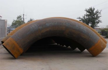
ASTM A234 WPB Pipe Bends
HGFF Group Co., LTD.has served various industries with its outstanding products and extraordinary services.
Design
The design of an induction pipe bend is an important part of the manufacturing process. The key elements of the design include the pipe diameter, wall thickness, bend radius, and angle of the bend. The designer must consider the application of the bend and the environment in which it will be used. For example, the design must take into account the pressure and temperature of the system, and the materials used must be compatible with the system. The designer must also consider the type of induction process to be used, as this will affect the design.
Material Selection
The material selection for induction pipe bends is an important step in the manufacturing process. The material must be compatible with the induction process, and must be able to withstand the pressure and temperature of the system. Common materials used include stainless steel, carbon steel, and aluminum.
Induction Process
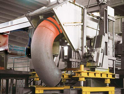
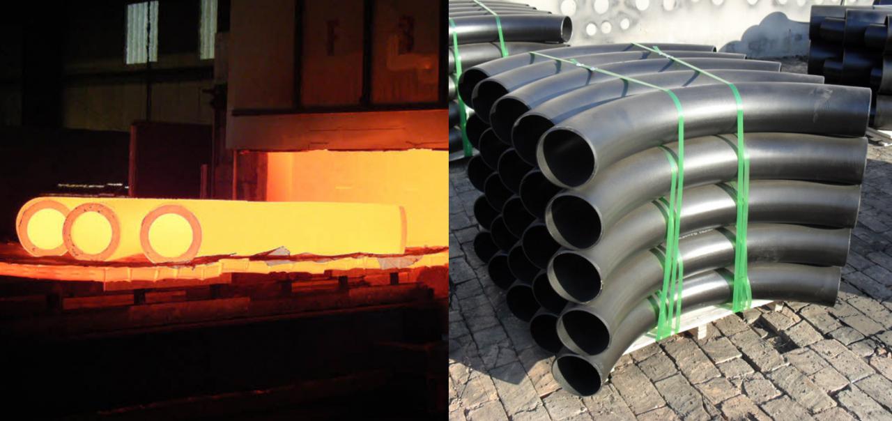
The induction process is the most important step in the manufacture of induction pipe bends. The process involves heating the material using an induction coil, which generates an electromagnetic field. The material is heated to a specific temperature and then bent into the desired shape. The process is highly precise and can produce bends with a very high degree of accuracy.
Finishing
Once the induction process is complete, the bend must be finished. This can involve polishing, coating, or other treatments to improve the appearance and performance of the bend. This step is important for ensuring the bend meets the required specifications and performs as expected.
Quality Control
Quality control is an essential part of the manufacturing process for induction pipe bends. The quality control process ensures that the bend meets the required specifications and that it performs as expected. Quality control tests may involve inspecting the bend for defects, measuring the bend for accuracy, and testing the bend for strength and durability.
Conclusion
Induction pipe bends are an important component in many industrial applications. The process of manufacturing induction pipe bends involves careful design, material selection, induction process, finishing, and quality control. These steps are essential for producing a quality bend that meets the required specifications and performs as expected.
PIPE BEND Specifications
| Specifications | ASTM A234 & ASME SA234, ASTM A420 & ASME SA420, ASTM A860 & ASME SA860 |
| Dimensions | ASME/ANSI B16.9 / B16.28 and MSS SP-43 / SP-75 |
| Size | Seamless Pipe Bends (1/2″ – 24″), ERW / Welded / Fabricated Pipe Bends (2″ – 36″) |
| Outer Diameter | 38.0 mm – 206.0 mm |
| Wall Thickness | 1.5 mm / 2.0 mm / 3.0 mm – greater wall thickness at request |
| Bend Radius | 75 / 100 / 150 / 250 / 300 / 500 / 800 / 1,000 / 1,200 / 1,500 mm |
| Bending Radius(R) | R=1D, 2D, 3D, 5D, 6D, 8D, 10D or Custom |
| Bending angle (θ) | 15°, 30°, 45°, 60°, 90°, 135°, 180° |
ASTM A234 WPB Carbon Steel Piggable Pie Bend Manufacturing Standards:
| ASME Pipe Bend | ANSI B16.9, ANSI B16.28, MSS-SP-43 |
| DIN Pipe Bend | DIN2605, DIN2615, DIN2616, DIN2617, DIN28011 |
| EN Pipe Bend | EN10253-1, EN10253-2 |
| ASME B16.9 | Factory-Made Wrought Fittings Buttwelding |
| ASME B16.25 | Buttwelding Ends ASME B16.28 – Wrought Steel Short Radius Elbows and Buttwelding Returns |
| MSS SP-43 | Wrought and Fabricated Butt-Welding Fittings for Low Pressure, Corrosion Resistant Applications |

You must be logged in to post a comment.