Induction Bending is a controlled means of bending pipes through the application of local heating using high frequency induced electrical power. The induction bending process was originally used during World War II to harden gear and ball bearing surfaces. Today, induction bending enables the bending of large pipes, including square and rectangular tubes.
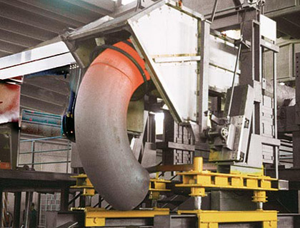
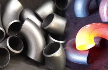
Originally used for the purpose of surface hardening steels, induction technology when used in pipe bending consists basically of an induction coil placed around the pipe to be bent. The induction coil heats a narrow, circumferential section of the pipe to a temperature of between 850 and 1100 degrees Celsius (dependant on the material to be formed). As the correct bending temperature range is reached, the pipe is moved slowly through the induction coil whilst the bending force is applied by a fixed radius arm arrangement.
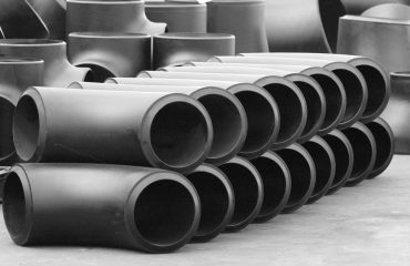
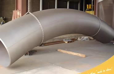
Induction bends come in standard bend angles (e.g. 45°, 90°, etc.) or can be custom made to specific bend angles. Compound bends (out-of-plane) bends in a single joint of pipe can also be produced. The bend radius is specified as a function of the diameter. For example, common bend radii for induction bends are 3D, 5D and 7D, where D is the nominal pipe diameter.
To create induction bends, induction pipe bending experts place an induction coil around a pipe. The coil heats a narrow section of pipe to 800 to 2,200 degrees Fahrenheit, depending on the material type. Once the proper temperature is reached, the pipe slowly passes through the coil as the bending force is applied. After the induction bends are formed, the heated area is cooled by a spray of water or air.
ASME B16.49
ASME B16.49 Standard covers design, material, manufacturing, testing, marking, and inspection requirements for factory-made pipeline bends of carbon steel materials having controlled chemistry and mechanical properties, produced by the induction bending process, with or without tangents.
This standard covers induction bends for transportation and distribution piping applications (e.g., ASME B31.4, B31.8, and B31.11). Process and power piping have differing requirements and materials that may not be appropriate for the restrictions and examinations described herein, and therefore are not included in this Standard.
Compared to cold forming methods, induction bending minimizes deformation of the material and distortion of the cross-section even when tight radius bends are required. This hot bending process is a preferred alternative to the traditional cold bending process as it limits wall thinning, rippling and ovality. It is the consistency and predictability of this bending process that contributes to the high quality and reliabity of bends. Heat induction bending enables the bending of large pipes, steel beams, as well as square and rectangular tubes.
Hot Induction Bend
Bend Type: Pipe Bend, Steel Pipe Bend, Hot Bend, Induction Bend, Induction Hot Bend
Material: carbon API 51, ASME 816.49, EN 10218 Alloy steel m ASTM A234
stainless steel ASTM 312/403 304/304L/316/316L/613Ti/321/317L/310S
Specification: NPS from 1/2″ to 72″, DN from 15 to 1800,
WT: <120mm, SCH 40/80/XXS
Induction Bending Process
Straight pipe is placed in the machine bed with an induction heating coil located around the pipe at one end. This heating coil creates a narrow, circumferential, heated band around the material. As the pipe reaches the required temperature, it is slowly pushed forward through the coil at a consistent speed and temperature and shaped into a bend. After the material passes through the coil, it is cooled by a controlled water cooling system.

Induction Bending,Hot Induction Bend


You must be logged in to post a comment.